Inverter PPT | PDF | PowerPoint Presentation: An inverter is nothing but a motor control which is used in adjusting the speed of an AC induction motor. The speed of the AC induction motor is adjusted by the frequency variation of the AC power to the motor. Inverter not only adjusts the speed but also adjusts the voltage to the motor. This process of adjustment is done availing few electronic circuits which control six distinct power machines.
They switch on and switch off to generate a pretended three-phase AC voltage. This process of switching is also known as inverting DC bus voltage and current into the waveforms which are in the form of AC and are applied to the motor. This feature has given the name inverter and this term inverter also replaces the term adjustable speed drive.
Inverter PPT | PDF | PowerPoint Presentation
Working of an Inverter:
Most of the inverters have the feature of varying voltage and varying frequency and from this, we can say that the inverters have variable voltage design and variable frequency design. They have three sections and those are as below:
- Converter section
- Inverting section
- Bus capacitor section
- Converter section: The converter section avails semiconductor machines to convert the fixed voltage that is the incoming fixed voltage and fixed frequency three phase AC power to DC voltage.
- Bus capacitor section: The incoming fixed voltage and fixed frequency three phase AC power to DC voltage which is converted are saved in the bank of bus capacitor. Here it becomes a source of current which is steady for the power machines that are present in the inverting section.
- Inverting section: Power from the DC bus cap bank is absorbed by the inverting section. After absorption, it inverts it back to the simulated three-phase AC sine waves which have varying frequency and varying voltage. These sine waves are availed to change the speed of a three phase induction motor.
The Block Diagram of an Inverter:
The block diagram of an inverter with the necessary block diagrams is explained in the below figure:
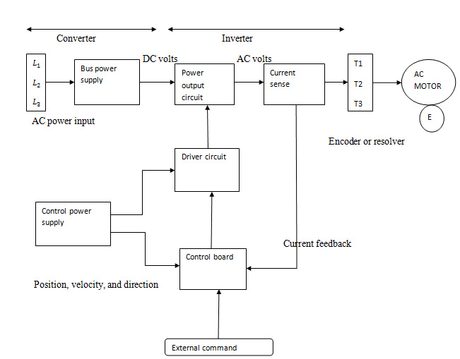
Fig1: Block Diagram of an Inverter
Voltage Source Inverters:
The single-phase voltage source inverter and the three-phase voltage source inverters need a single dc source, for the medium output power applications the selected machines are n-channel IGBTs. The components in it are explained below:
- – input dc supply
- – Large dc link capacitor
- , and – fast and controllable switches
- , and – fast recovery diodes
- A, B, and C – output terminals of the inverter
- Three-phase inverter has three load-phase terminals
- Single-phase inverter has one pair of load terminals
- Capacitors and switches are connected to the dc bus by availing short leads
- – dc link current
The short lead connections of capacitors and switches to the dc bus reduce the stray inductance between the inverter switches and capacitor. The dc link current is nothing but the current supplied to the inverter switches by the dc bus. If an ideal dc input supply does not have the series impedance then the dc link capacitor have no role. The dc link capacitor has to be close to the switches because it furnishes a low impedance path to the component of the high frequency of the switch currents. The capacitor should have to be of a good quality with the parameters like very low equivalent series inductor ESL and also with very low equivalent series resistor ESR.
Classification of Voltage Source Inverters:
The voltage source inverters are classified by depending on distinct criteria and those are explained below:
- A number of phases they output like single-phase or three-phase or two-phase or five-phase by depending on the output they give.
- The inverters are also classified on the ability of inverters in governing the magnitude of output parameters like harmonic content, voltage, and frequency etc.
- Few inverters can give the output of fixed magnitude and where as few can give the output to a variable frequency and variable voltage.
- Inverters are also classified based on the topologies.
- Few voltage source inverters give the output in low order harmonics like 3rd, 5th, 7th, 11th, and 13th
- Few voltage source inverters are free from the output of low order harmonics but they can have corruption of high order harmonics.
Content of the PPT and PDF for Inverter
- What is an inverter
- History of inverter
- Application of inverters
- What kind of inverter do I want?
- Use of inverters
- Classification of inverter
- Single phase full wave inverter
- Static Inverter
- Dynamic inverter
- Characteristics of good inverter
- Conclusion
- References
Here we are giving you Inverter PPT with PDF. All you need to do is just click on the download link and get it.
It was all about Inverter PPT with PDF. If you liked it then please share it or if you want to ask anything then please hit comment button.